PCB Assembly - Building a BLDC Driver
First Try on Making a PCB
October 2023 - November 2023
ECE1100 Discovery Project
Project EDA Soldering Electronics
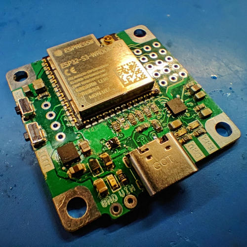
In this discovery project, I want to go through the design, manufacturing, and assembly of a PCB board all by myself. That's why I decided to build a Brushless Motor Driver using the provided design files from SimpleFOC online. I ordered the compoenents, carried out solder-pasting and retroflowing soldering, and finally finished some basic teseting on the board.
Initiatives
I want build a simple Brushless Direct Current Motor (BLDC) driver. One of the reason is that many of robotics application requires universal BLDC drivers as the base of any other control algorithms. Making such a board will help me to gain some basic understanding of the theories lying behind the controller, paving the path for my future robotics projects.
At the same time, I do not have any prior experience making PCB boards. I only soldered some of the parts onto the PCB, but I've never gone through the whole process - design, manufacturing, assembly, verification, and finally application. This project gives me one of the chances to finish this workflow, preparing me for my future ECE projects & DIYs.
Practice Soldering
Before I get started, I spent some time practicing my soldering skills. As the components on the BLDC driver board is pretty expensive, I want to make sure that I do things right.
I practiced doing 50 resistors & 50 LEDs by hand and with the retroflow machine. The result is a success: the resistors and LEDs have connectivity and they are working fine under 5v of voltage input.
Research & Component Ordering
I find various solutions for BLDC drivers online. Usually, for driving a BLDC motor, the current angle of the motor matters - as it will determine which stator should be powered to push the motor. I want to choose an integrated solution that is able to measure the angle and drive the motor at the same time.
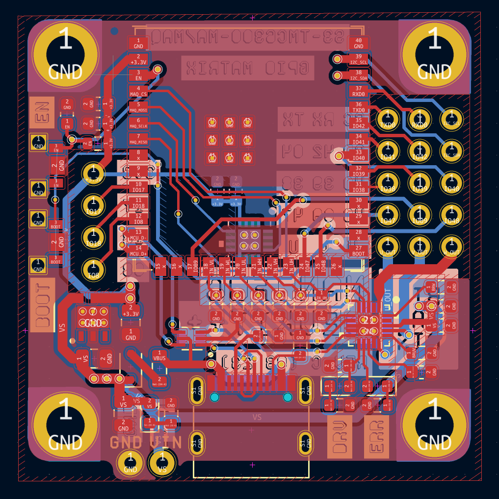
My final selection is NanoFOC. It is an extremely compact BLDC driver with FOC equipped. I spent a few week learning and reading the schematic diagrams & ordering the components.
Stencil Making & Retroflow Soldering
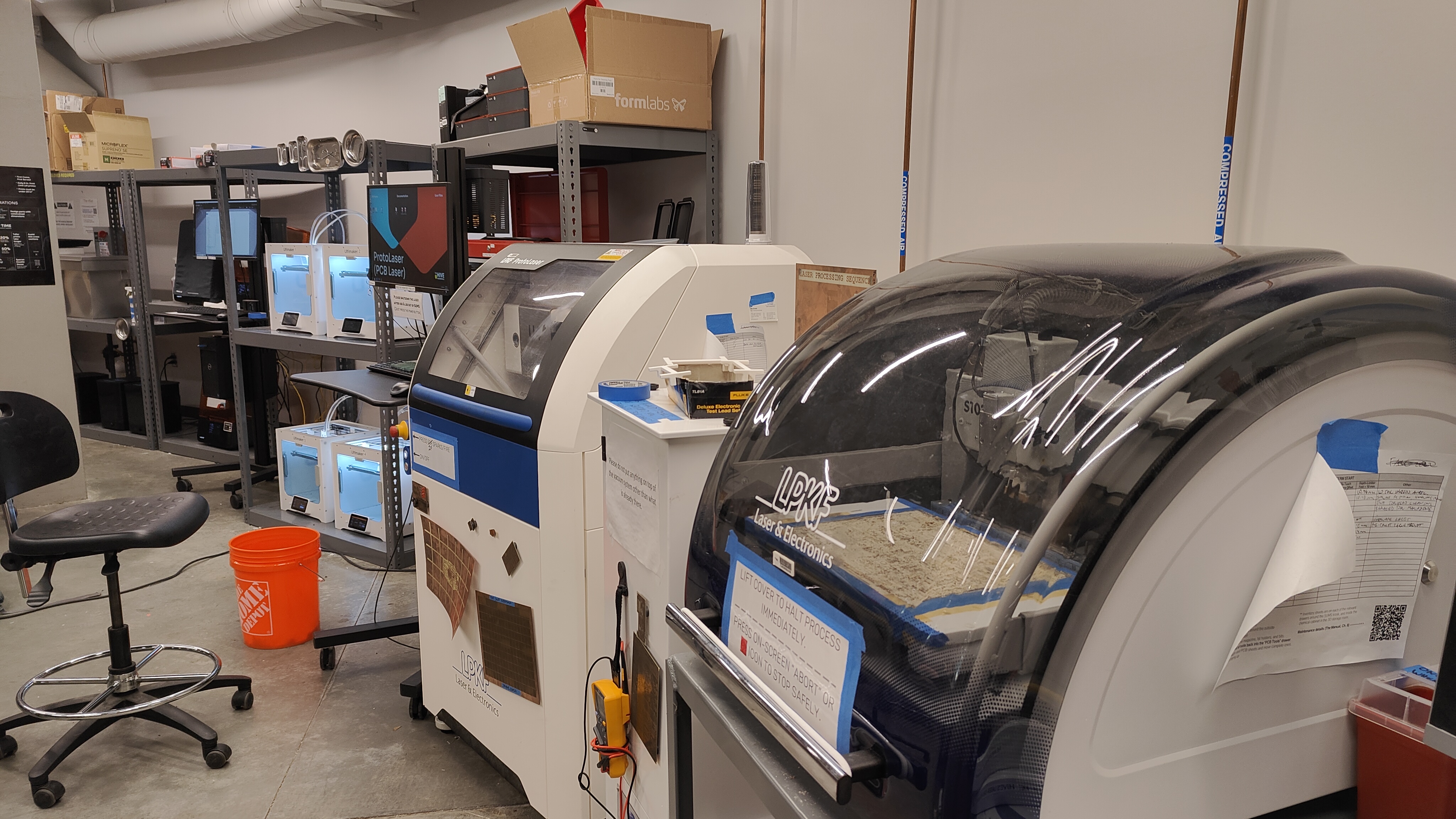
After the components arrived, I started to make stencils to make solder pastes get onto the PCB board. I utilized the Protolaser PCB machine at the HIVE for making stencils. At the same time, I learned about how to make a prototype double-sided PCB using that machine.
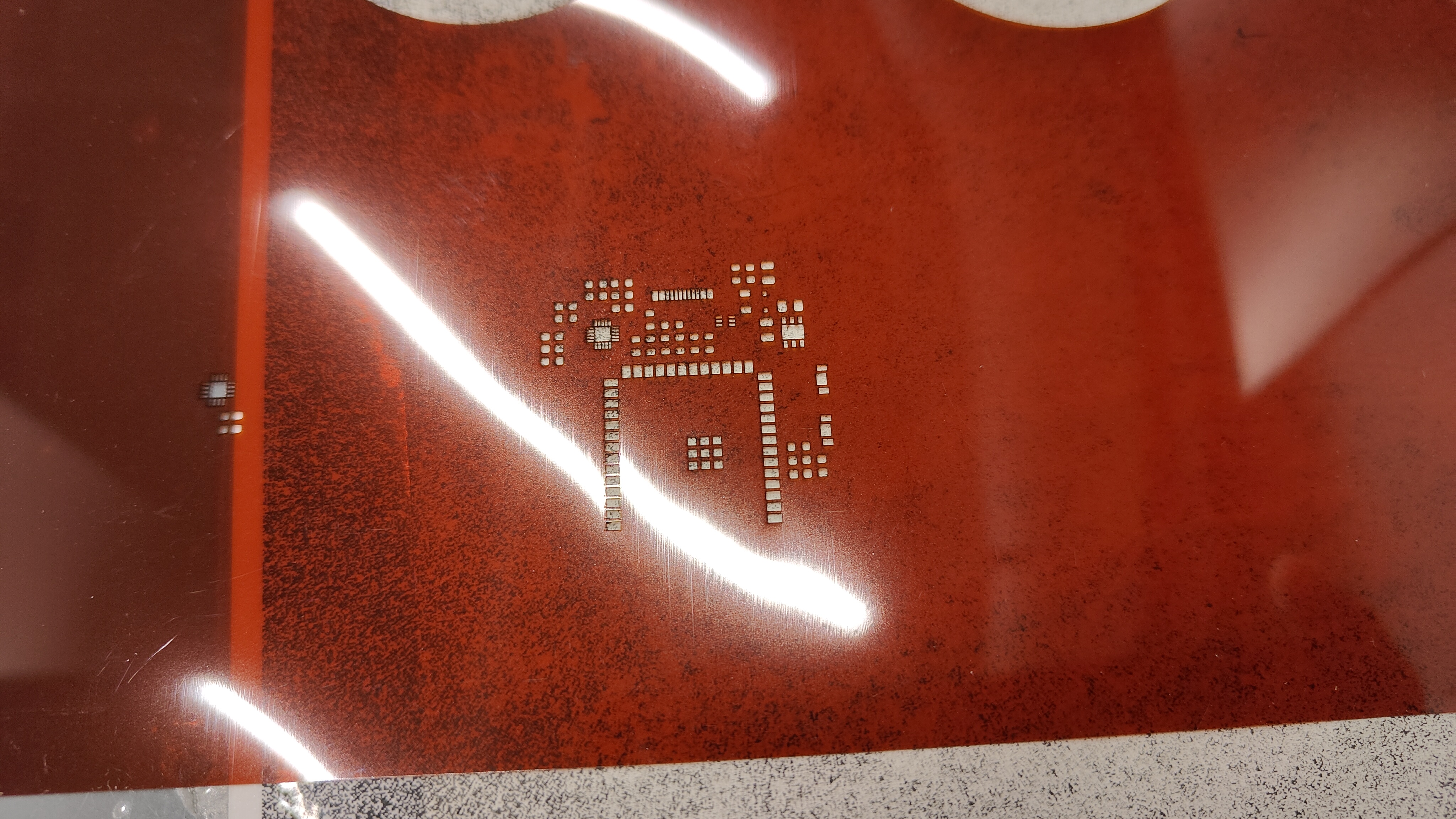
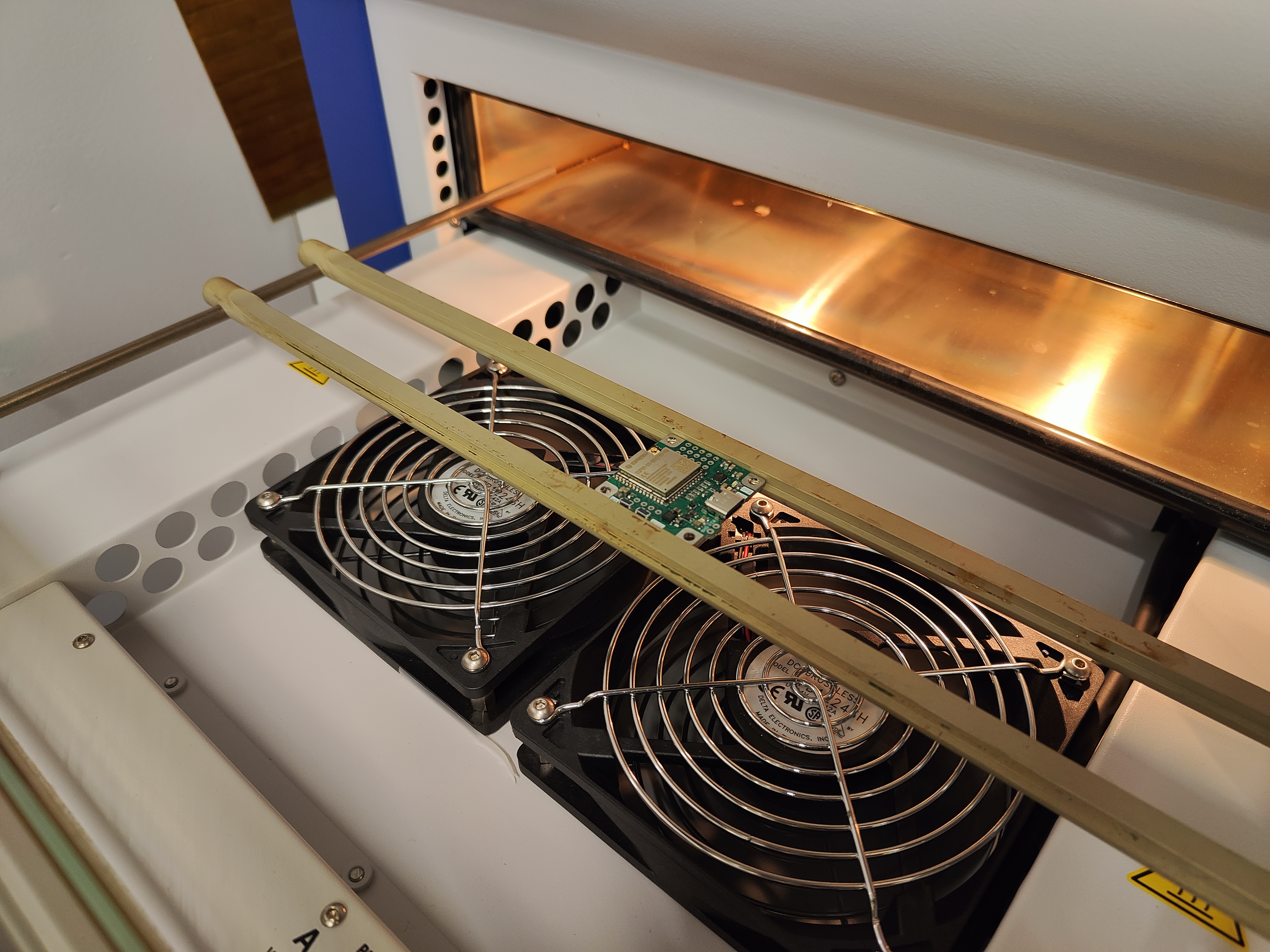
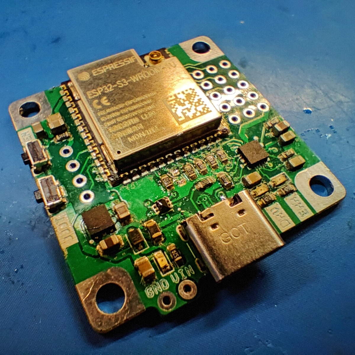
After that, I spread solder paste to the pads using the stencil I made and spent a few hours putting components onto the soldering pads. Then, the PCB is put into the retroflow machine for soldering.
Something worth noting is that this PCB is double-sided, which increases the difficulty of retroflow soldering, as the components on the back might fall off. To solve that problem, I used heat-resistant tape to fix the MAQ430 chip in place when I'm soldering the upper side of the PCB board.
Board Testing
The board can boot up and load the program. I tried some simple hello world programs via Serial port, the board can be flashed and respond to what I've entered in the serial window.

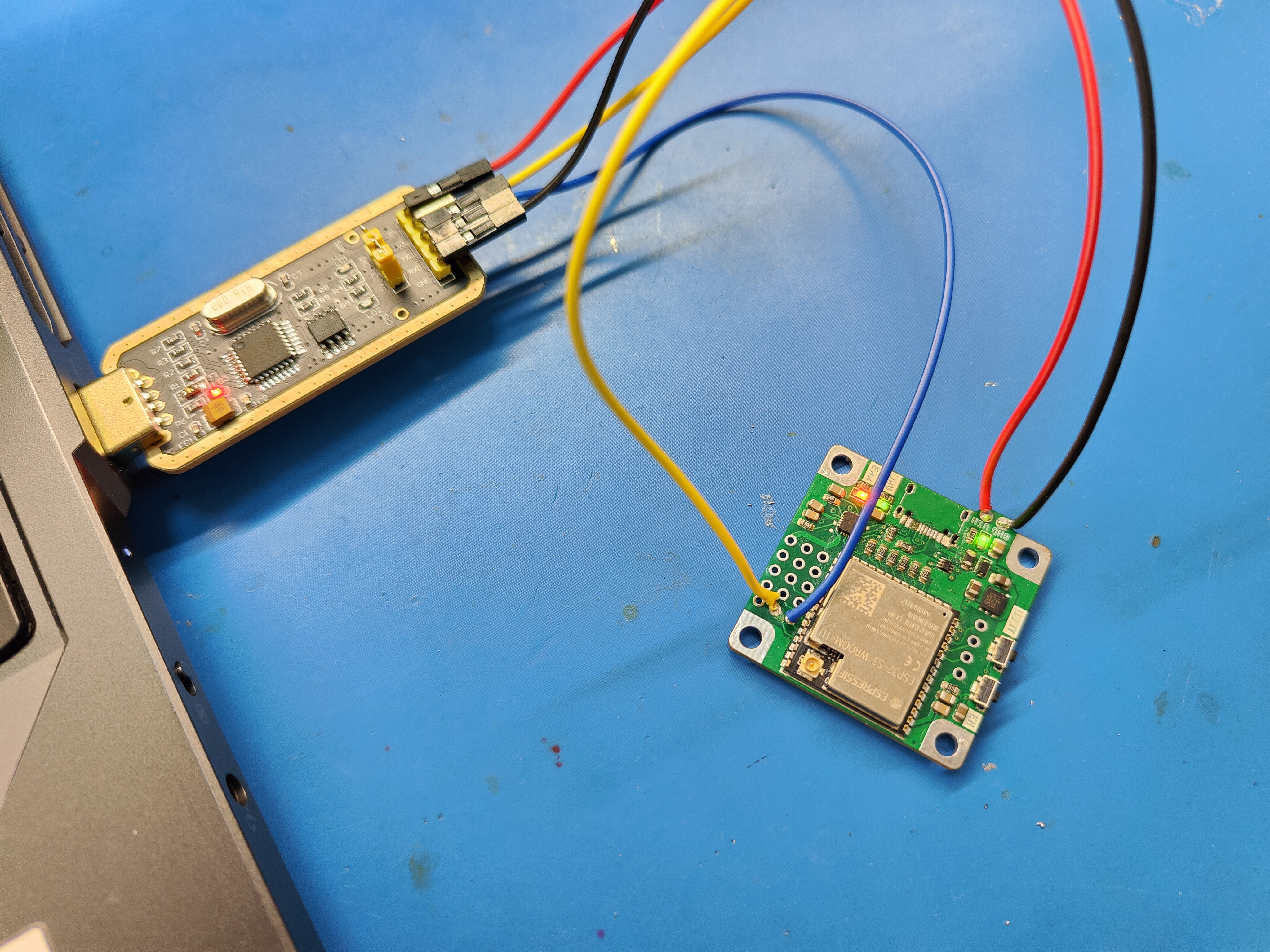
Unfortunately, the board's USB port snaps after a few connections. During that catastrophic failure, the soldering pad on the PCB also gets off, which means that I'm not able to connect to the board again. At the same time, the UART connection method to the board is not able to work.
Reflection & Potential Improvements
The project is not so successful in terms of the application. I'm not able to carry out comprehensive testing on the motor due to the breakage of the board.
However, via this project, I still gained precious experience in building PCBs. I go through the whole process successfully, finally making a usable PCB. I also learned about the potential points of improvement during the process of making PCB board, and this might aid me in future ECE and diy projects.